

| ISO CLASS ISO 14644 | FEDERAL STANDARD | MAXIMUM PARTICLES PER M3 (PER PARTICLE SIZE SHOWN BELOW) | ||||||||||
| ≥ 0.1 µm | ≥ 0.2 µm | ≥ 0.3 µm | ≥ 0.5 µm | ≥ 1.0 µm | ≥ 5.0 µm | |||||||
| ISO 1 | 10 | |||||||||||
| ISO 2 | 100 | 24 | 10 | 4 | ||||||||
| ISO 3 | Class 1 | 1000 | 237 | 102 | 35 | 8 | ||||||
| ISO 4 | Class 10 | 10000 | 2370 | 1020 | 352 | 83 | ||||||
| ISO 5 | Class 100 | 100000 | 23700 | 10200 | 3520 | 832 | 29 | |||||
| ISO 6 | Class 1,000 | 1000000 | 237000 | 102000 | 35200 | 8320 | 293 | |||||
| ISO 7 | Class 10,000 | 352000 | 83200 | 2930 | ||||||||
| ISO 8 | Class 100,000 | 3520000 | 832000 | 29300 | ||||||||
| ISO 9 | 35200000 | 8320000 | 293000 | |||||||||
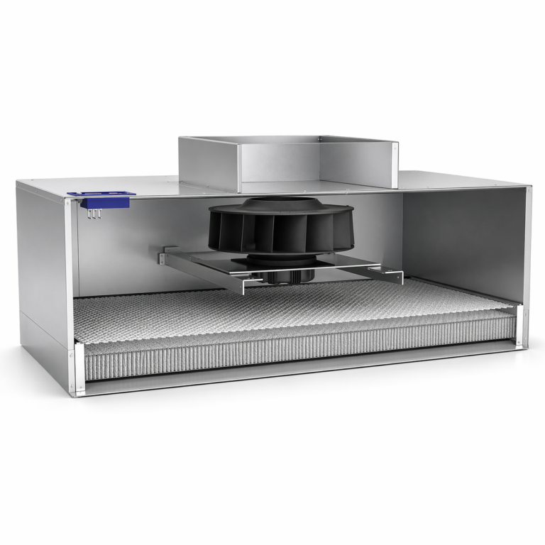
| Model | W x L x H | Total Static Pressure | Power Consumption | Air Velocity | Noise Level | Vibration Level |
|---|---|---|---|---|---|---|
| (ft) | (Inch w.g.) | (W) | (fpm) | (dB(A)) | (inch/s) | |
| F-22AL | 2' x 2' | 1.0 | 80 | 90 | 50.0 | 0.0276 |
| F-23AL | 2' x 3' | 0.8 | 110 | 90 | 51.0 | 0.0314 |
| F-24AL | 2' x 4' | 0.8 | 120 | 90 | 52.0 | 0.0394 |
| F-24AM | 2' x 4' | 1.2 | 155 | 90 | 53.0 | 0.0394 |
| F-34AM | 3' x 4' | 1.0 | 175 | 90 | 53.5 | 0.0472 |
| F-34AM1 | 3' x 4' | 1.1 | 225 | 90 | 53.0 | 0.0472 |
| F-44AM1 | 4' x 4' | 0.8 | 245 | 90 | 55.0 | 0.0472 |
| F-44AH | 4' x 4' | 1.1 | 305 | 90 | 53.5 | 0.0472 |
| Model | W x L x H | Total Static Pressure | Power Consumption | Air Velocity | Noise Level | Vibration Level |
Remark:
1. Test point of noise level is located at 1.5 m (equivalent to 4.9 ft) below the filter downstream.
2. Test point of air velocity is located at 0.15 m (equivalent to 0.49 ft) below the filter.
3. FFU sizes can be customized upon request.
4. FFU power consumption listed are calculated based on FFU intial performance.
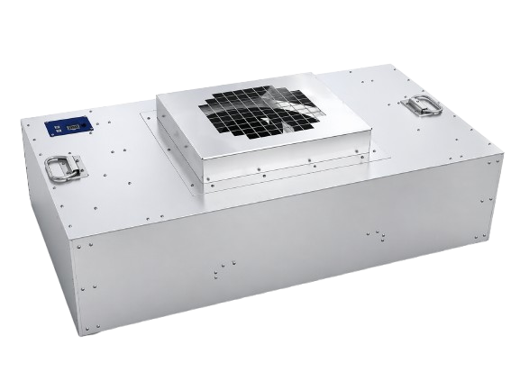
| Model | W x L x H | Total Static Pressure | Power Consumption | Air Velocity | Noise Level | Vibration Level |
|---|---|---|---|---|---|---|
| (ft) | (Inch w.g.) | (W) | (fpm) | (dB(A)) | (inch/s) | |
| F-22EL | 2' x 2' | 1.1 | 55 | 90 | 49.0 | 0.0236 |
| F-23EL | 2' x 3' | 1.0 | 70 | 90 | 50.5 | 0.0236 |
| F-24EL | 2' x 4' | 0.8 | 85 | 90 | 51.5 | 0.0314 |
| F-24EH | 2' x 4' | 1.5 | 90 | 90 | 51.0 | 0.0314 |
| F-34EH | 3' x 4' | 1.4 | 125 | 90 | 52.5 | 0.0314 |
| F-44EH | 3' x 4' | 1.4 | 180 | 90 | 53.5 | 0.0314 |
| Model | W x L x H | Total Static Pressure | Power Consumption | Air Velocity | Noise Level | Vibration Level |
Remark:
1. Test point of noise level is located at 1.5 m (equivalent to 4.9 ft) below the filter downstream.
2. Test point of air velocity is located at 0.15 m (equivalent to 0.49 ft) below the filter.
3. FFU sizes can be customized upon request.
4. FFU power consumption listed are calculated based on FFU intial performance.
The MayAir Flonet system is well-suited for efficiently managing a clean room of any size and is able to control both AC and EC types of FFUs.
It offers real-time monitoring and can handle up to 50,000 units within a single system. This system is versatile, allowing control over the entire building’s cleanroom, including separate zones with varying ISO classes. It utilizes a TCP/IP network for signal transmission at speeds of up to 100Mbps, with the option for fiber optic configuration. The system exhibits exceptional stability and response times, with synchronous FFU group scanning taking less than 15 seconds per cycle, and it continues to operate seamlessly even in the event of a lost connection to the server or PC.
MayAir places a strong emphasis on security and has developed a multi-level administration system for control and monitoring. Users receive a unique registration key for software commissioning. User-friendliness is a top priority in the software’s design, featuring a clear navigation tree and a display of theactual cleanroom layout. This ensures users have a more efficient and straightforward experience when monitoring FFUs within the cleanroom.